- Boss design - REMFORM® II HS™
- Boss dimensions - REMFORM® II F™
- Boss dimensions - CELOspArk®
- Aluminum die casting - TAPTITE 2000®
- Aluminum and Magnesium die casting - REMFORM® II F™
- Aluminum die casting - TAPTITE II®
Boss design for CELOspArk®
In order to ensure a safe installation and stable clamping force, it is relevant to pay attention to the boss design, as it must resist mold extraction and cooling tension as well as tension created during screw installation.
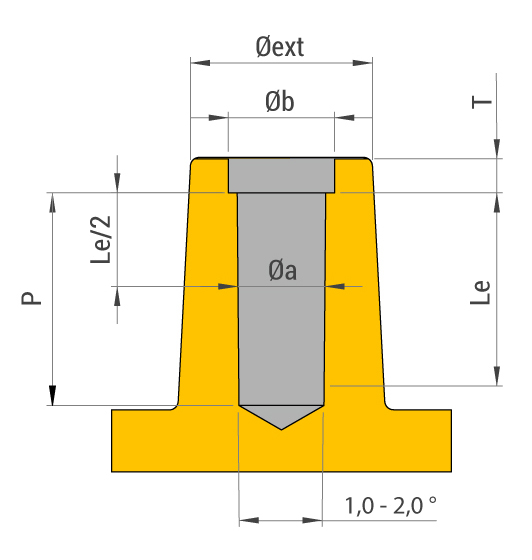
It’s important to include a relief bore to prevent damaging the boss when starting thread forming. The relief bore also helps to align the screw during threading.
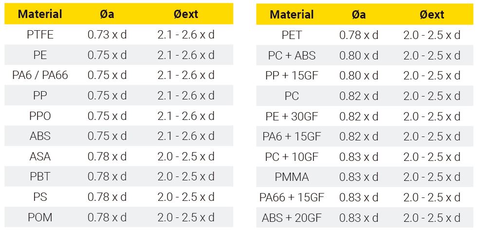
The dimensions for external diameter, core hole diameter and minimum depth will vary based on the type of plastic.
d = screw diameter
Øa = core hole diameter
Øext = external diameter
Length of engagement Le = 2.3 x d
Minimum depth P = 2.9 x d
Relief bore height T = 0.25 - 0.5 x d
Relief bore external diameter Øb = 1.05 - 1.1 x d
Suggested tolerances:
+0.08 mm for holes ≤ Ø3.0 mm
+0.10 mm for holes Ø3.0 - Ø4.5 mm
+0.12 mm for holes > Ø4.5 mm

This data is intended for guidance purposes. We recommend carrying out relevant tests on plastic parts to establish the precise values.
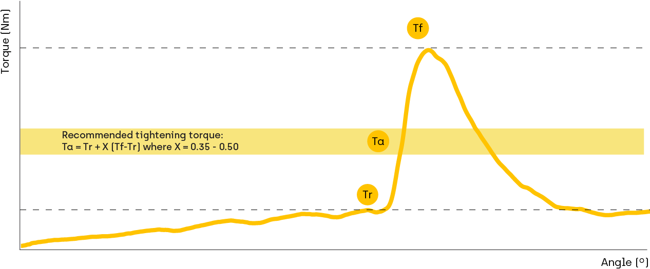
Assembly recommendations

Tr = Threading torque
Ta = Tightening torque
Tf = Failure torque
For additional information about the boss design for direct assembly in plastic parts, please contact our technical department.


