- Boss design - REMFORM® II HS™
- Boss dimensions - REMFORM® II F™
- Boss dimensions - CELOspArk®
- Aluminum die casting - TAPTITE 2000®
- Aluminum and Magnesium die casting - REMFORM® II F™
- Aluminum die casting - TAPTITE II®
Pilot hole diameter in steel sheet for TAPTITE 2000®
1. Recommended pilot hole diameter for extruded holes.
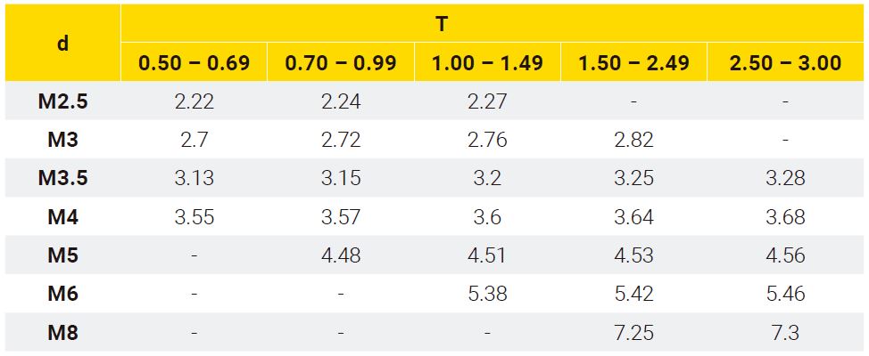
The following tables show the recommended pilot hole diameter for different plate thickness with extruded holes.
This data is intended for guidance purposes. We recommend carrying out relevant tests on definitive parts to establish the precise values. The size of the extrusion can vary depending on the material used and tool design. Dimensions in mm.
For additional information, please, contact our technical department.
Table 1. Pilot hole diameter in steel sheet with extruded holes.
d = Screw diameter
Ø = Pilot hole diameter
T = Plate thickness
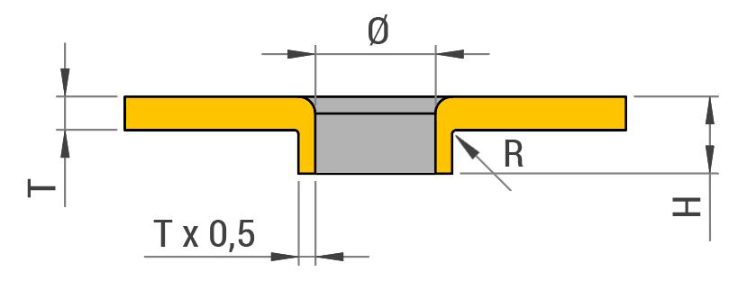
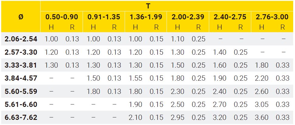
H = Flange height
Table 2. Height and radius of extruded holes in metal sheet from a given pilot hole diameter.
Suggested tolerances:
+0.03/-0.04 mm for Ø<2.0 mm
+0.03/-0.05 mm for Ø2.0 - Ø5.0 mm
+0.04/-0.05 mm for Ø5.1- Ø7.0 mm
+0.05/-0.08 mm for Ø>7.0 mm
H: +0.40 mm
Example: Assembly on metal sheet of 0.6 mm thickness with M3 screw. Following the recommendations from Table 1, we should make 2.7 mm pilot hole diameter, and as shown in Table 2, flange height (H) would be 1.2 mm and radius (R) 0.13 mm.
We recommend using FASTITE®2000™ screws or extruded holes for the assembly of thin metal sheet. Extruded holes nearly double the length of thread engagement over original material thickness with the objective to increase resistance to stripping and vibrational loosening.
2. Recommended pilot hole diameter in steel sheet.
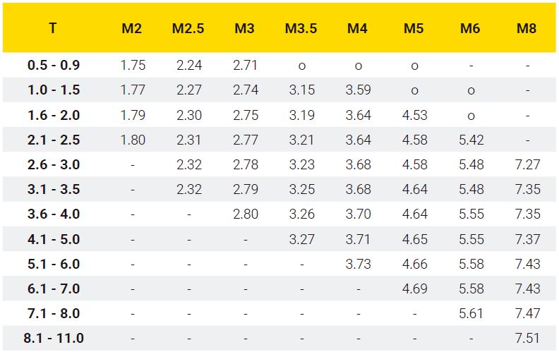
The following tables show the recommended pilot hole diameter for different plate thickness and screw diameters.
This data is intended for guidance purposes. We recommend carrying out relevant tests on definitive parts to establish the precise values. Dimensions in mm.
For additional information, please, contact our technical department.

Ø = Pilot hole diameter
T = Plate thickness
Suggested tolerances:
+0.03/-0.04 mm for Ø<2.0 mm
+0.03/-0.05 mm for Ø2.0 - Ø5.0 mm
+0.04/-0.05 mm for Ø>5.0 mm


